Gambrel Truss [A Structural Guide]
Gambrel Trusses are commonly used in barn and building structures.
But why is that? Why is in some designs the Gambrel Truss favoured over the Fink or King Post Truss?
To get an answer to those questions, we need to understand the structural system and how the loads travel through its different members.
So in this post, we’ll show what the Gambrel Truss is, its static system(s), which members act in compression or tension and calculate the internal forces.
Alright, let’s talk GAMBREL TRUSSES. 🚀🚀
What Is a Gambrel Truss?
A gambrel truss is a type of roof truss with a double-sloped design, commonly used in barns and other agricultural buildings. It has a steeper upper slope and a shallower lower slope.
Let’s have a look at the Gambrel Truss and its members.⬇️⬇️
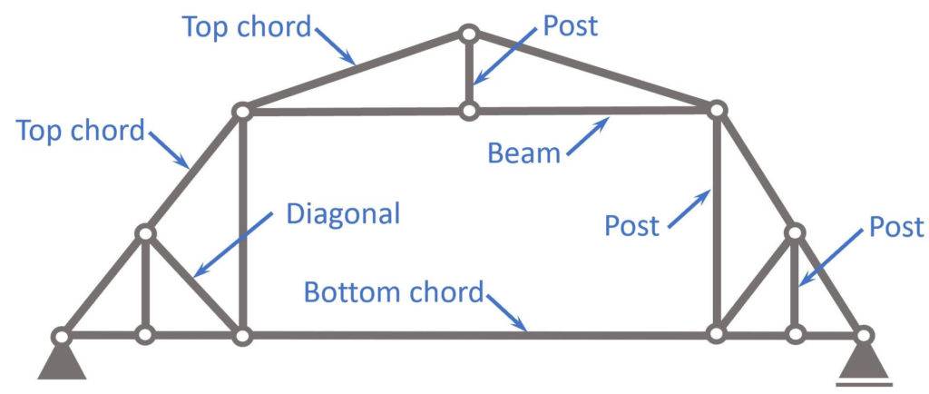
- Top chord/ rafter
- Posts
- Bottom chord
- Diagonals
- Beam
What is the Gambrel Truss used for?
Gambrel trusses are mainly used as roof structures of
- Sheds
- Garages or
- other agricultural structures.
In most cases, timber is the main material, however steel could also be an option.
Let’s look at the static system to get a better understanding of the structural behaviour of this truss type.🚀🚀
Static System
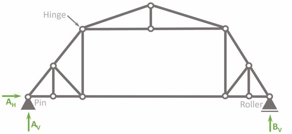
The static system of the Gambrel Truss is characterized by having
- hinge connections at all nodes
- a pin and roller support, which makes the system statically determinate. Therefore, the internal forces can be calculated with the 3 equilibrium equations.
Hinges
Most truss structures are designed with hinge connections, mainly due to 2 reasons:
- Easier to calculate: Trusses with hinge connections make the structure statically determinate, which means that the internal forces can be calculated by hand. Especially until advanced Finite element software programs weren’t widely available, this was the main reason for using hinge connections. If fixed connections are used, but no software is available, advanced methods like the method of consistent deformation can be used. However, these methods are complicated and susceptible to calculation failures.
- Cost: Hinge connections are cheaper to build than fixed connections.
💡💡 It definitely makes sense to be aware of the differences of a truss with hinges and fixed connections. In the picture above, you can see the “normal” gambrel truss with hinge connections.
We also summarize the characteristics of the truss with fixed connections and a mix of fixed and hinge connections a bit further below.
Characteristics
Loads
In most cases, the gambrel truss is used as a roof structure, where dead, snow, wind and live loads are applied on the rafters.
Support types
1 Pin and 1 Roller support
Reactions
Pin support: Horizontal AH and vertical reaction force AV
Roller support: Vertical reaction force BV
Connection types
Hinge connections: Moment is 0 in hinge connections.
Gambrel Truss with fixed connections
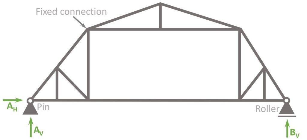
The Gambrel truss with fixed connections has the following differences to hinge connections:
- Bending moments in the connections
- More rigidity -> more robustness
- Smaller vertical deflection
Gambrel Truss with fixed and hinge connections
The most realistic static system is actually a mix of fixed and hinge connections.
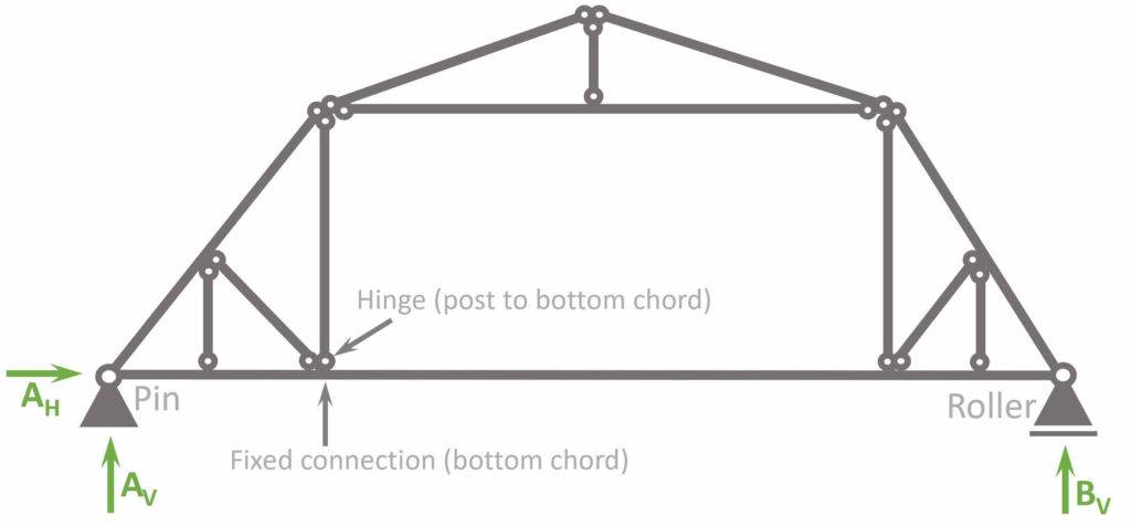
So why is this the most realistic static system?
It’s because usually elements like the top and bottom chords are delivered in one piece, meaning that they are constructed continuous and the post is attached to them.
The lower rafters basically turn into a 2-span continuous beam, which means that the static system is no longer statically determinate.
This means that advanced methods with FE programs need to be used to calculate the internal forces like Moment, Normal and Shear forces.
Alright, now that we have learned how to set up our static system, we are ready to calculate the internal compression and tension forces of the statically determinate truss.🎉🎉
Gambrel Truss Analysis
Let’s say our Gambrel Truss is a roof structure. Therefore, the truss is exposed to the snow load only on the rafters.
We also simplify and say that the load is 2 kN/m. This equals a snow load of 1 kN/m2 and a truss spacing of 2m. Check out this article to learn more about the snow load.
$$1 kN/m^2 \cdot 2m = 2 kN/m$$
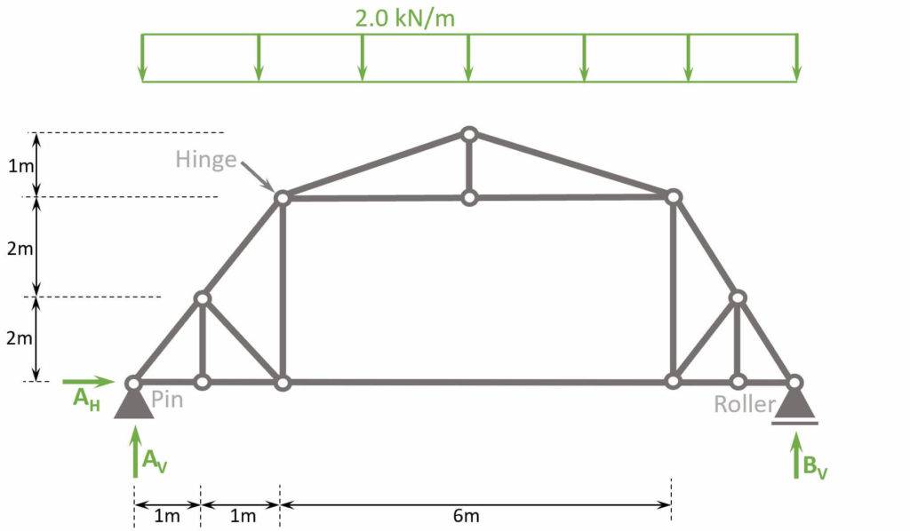
Before we start with the calculations, let’s give the nodes 🔵 and bars 🔴 some indices, so the identification is easier later in the internal force calculation.
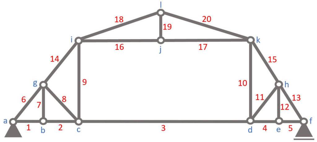
To calculate the compression and tension forces of the truss members with the 3 equilibrium equations, we do another approximation.
The Line load of 2 kN/m is approximated as point loads ⬇️⬇️ in the nodes, because otherwise the rafters (top chords) would be beams instead of bars, which makes the calculation a lot more difficult.
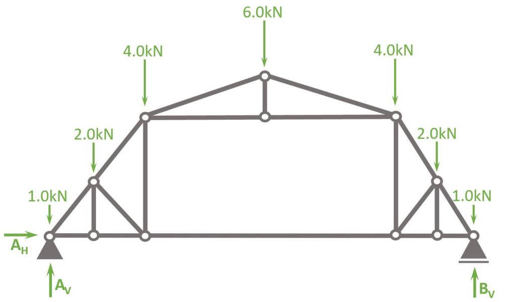
The point load applied to nodes (a) and (f) is calculated as
$$2 kN/m \cdot 0.5m = 1 kN$$
❗But be careful. The point loads are only transformed like this for the snow load. Dead, wind and live load are applied differently. Check out our article about how to apply loads to roofs.
The point loads applied to nodes (g) and (h) are calculated as
$$2 kN/m \cdot 1m = 2.0 kN$$
The point loads applied to nodes (i) and (k) are calculated as
$$2 kN/m \cdot (0.5m + 1.5m) = 4.0 kN$$
and the point load applied to (l) is calculated as
$$2 kN/m \cdot 3m = 6.0 kN$$
Let’s calculate. 🚀🚀
Calculation of Reaction Forces
As the structure is statically determinate, the reaction forces can be calculated with the 3 Equilibrium equations.
In our case, we are calculating the support forces AH, AV and BV.
$\sum H = 0: A_H = 0$
$\sum V = 0: A_V + B_V \, – 2 \cdot 1.0 \, \mbox{kN} \, – 2 \cdot 2.0 \, \mbox{kN} – 2 \cdot 4.0 \, \mbox{kN} – 6.0 \, \mbox{kN}= 0 $ -> $A_V = B_V = \frac{2 \cdot 1.0 + 2 \cdot 2.0 + 2 \cdot 4.0 + 6.0}{2} \mbox{kN} = 10 \mbox{kN}$
$\sum M = 0: M_a = 0$
Calculation of the internal forces
Node a
Alright, now that we know the reaction forces, we can calculate the normal force of the first bar elements 1 and 6.
To do that, we only look at node (a) and its point loads/normal forces AV, 1.0 kN, N1 and N6.
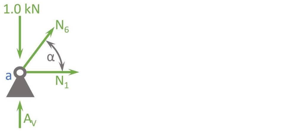
$$\alpha = atan(\frac{2m}{1m}) = 63.43° $$
Vertical Equilibrium:
$$ \sum V = 0: A_v – 1.0 kN + N_6 \cdot sin(\alpha) = 0$$
Let’s solve that for N6.
$$ N_6 = \frac{-A_v + 1 kN}{sin(\alpha)} = -10.06 kN$$
Horizontal Equilibrium:
$$\sum H = 0: N_1 + N_6 \cdot cos(\alpha) = 0$$
Let’s solve that for N1.
$$N_1 = -N_6 \cdot cos(\alpha) = 4.5kN$$
Node b
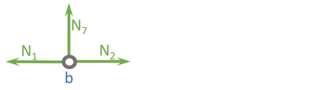
Vertical Equilibrium:
$$ \sum V = 0: N_7 = 0$$
Horizontal Equilibrium:
$$\sum H = 0: -N_1 + N_2 = 0$$
Let’s solve that for N2.
$$N_2 = N_1 = 4.5kN$$
Node f
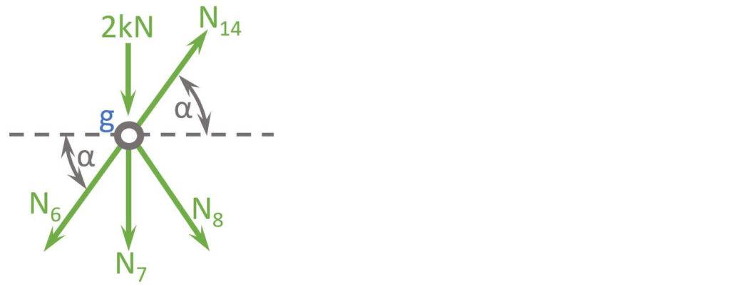
$$ \alpha = 36.9° $$
Horizontal Equilibrium:
$$\sum H = 0: N_{14} \cdot cos(\alpha) – N_6 \cdot cos(\alpha) + N_8 \cdot cos(\alpha) = 0$$
Let’s solve that for N14.
$$N_{14} = N_6 – N_8$$
Vertical Equilibrium:
$$ \sum V = 0: 2 kN + N_7 + N_6 \cdot sin(\alpha) + N_8 \cdot sin(\alpha) – N_{14} \cdot sin(\alpha) = 0$$
Let’s insert the expression for N14 from the horizontal equilibrium.
$$2 kN + N_6 \cdot sin(\alpha) + N_8 \cdot sin(\alpha) – (N_6 – N_8) \cdot sin(\alpha) = 0$$
Let’s solve that for N8.
$$N_8 = – \frac{2kN}{2 sin(\alpha)} = -1.12 kN$$
And N14 is found as
$$N_{14} = N_6 – N_8 = -8.9 kN$$
Node c
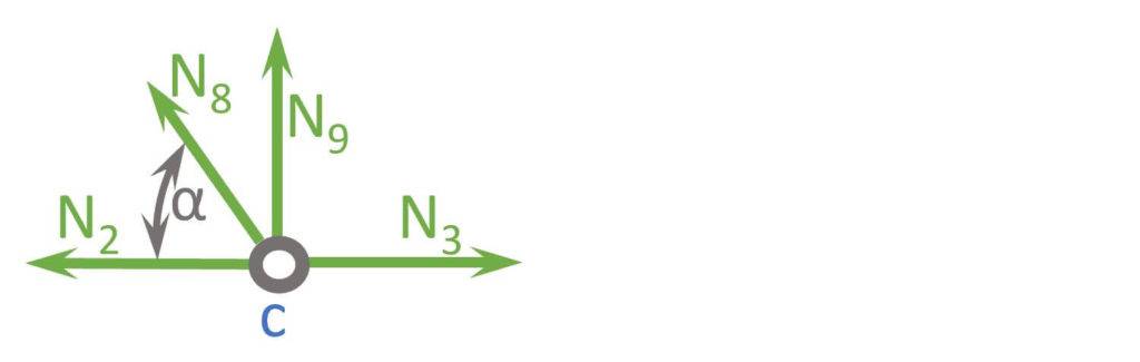
$$\alpha = 63.43° $$
Vertical Equilibrium:
$$ \sum V = 0: N_9 + N_8 \cdot sin(\alpha) = 0$$
Let’s solve that for N9.
$$ N_9 = -N_8 \cdot sin(\alpha) = 1 kN$$
Horizontal Equilibrium:
$$\sum H = 0: N_2 + N_8 \cdot cos(\alpha) – N_3 = 0$$
Let’s solve that for N3.
$$N_3 = N_2 + N_8 \cdot cos(\alpha) = 4.0kN$$
Node i
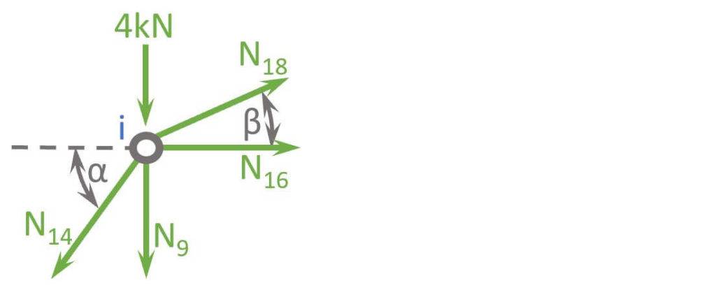
$$\alpha = 63.43° $$
$$\beta = atan(\frac{1m}{3m} = 18.43° $$
Vertical Equilibrium:
$$ \sum V = 0: 4 kN + N_9 + N_{14} \cdot sin(\alpha) – N_{18} \cdot sin(\beta) = 0$$
Let’s solve that for N18.
$$ N_{18} = \frac{4kN + N_9 + N_{14} \cdot sin(\alpha)}{sin(\beta)} = -9.49 kN$$
Horizontal Equilibrium:
$$\sum H = 0: N_{16} + N_{18} \cdot cos(\beta) – N_{14} \cdot cos(\alpha) = 0$$
Let’s solve that for N16.
$$N_{16} = -N_{18} \cdot cos(\beta) + N_{14} \cdot cos(\alpha) = 6.0kN$$
Node l
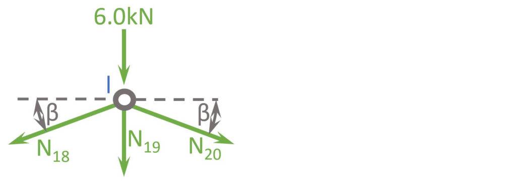
$$\beta = 18.43° $$
Horizontal Equilibrium:
$$\sum H = 0: N_{18} \cdot cos(\beta) – N_{20} \cdot cos(\beta) = 0$$
Let’s solve that for N20.
$$N_{20} = N_{18} = -9.49kN$$
Vertical Equilibrium:
$$ \sum V = 0: 6 kN + N_{19} + N_{18} \cdot sin(\beta) + N_{20} \cdot sin(\beta) = 0$$
Let’s solve that for N19.
$$ N_{19} = -6 kN – N_{18} \cdot sin(\beta) – N_{20} \cdot sin(\beta) = 0$$
🎉🎉Well done! Now we have calculated the normal forces of ALL bars.🎉🎉
What all? But we are missing half of the bars.
Yes! But due to symmetry we know that N1 = N5, N2 = N4, N6 = N13, N7 = N12, N8 = N11, N9 = N10, N14 = N15, N16 = N17, N18 = N20.
So, to summarize it, a normal force diagram helps to understand how the loads travel through the truss.
Normal force diagram
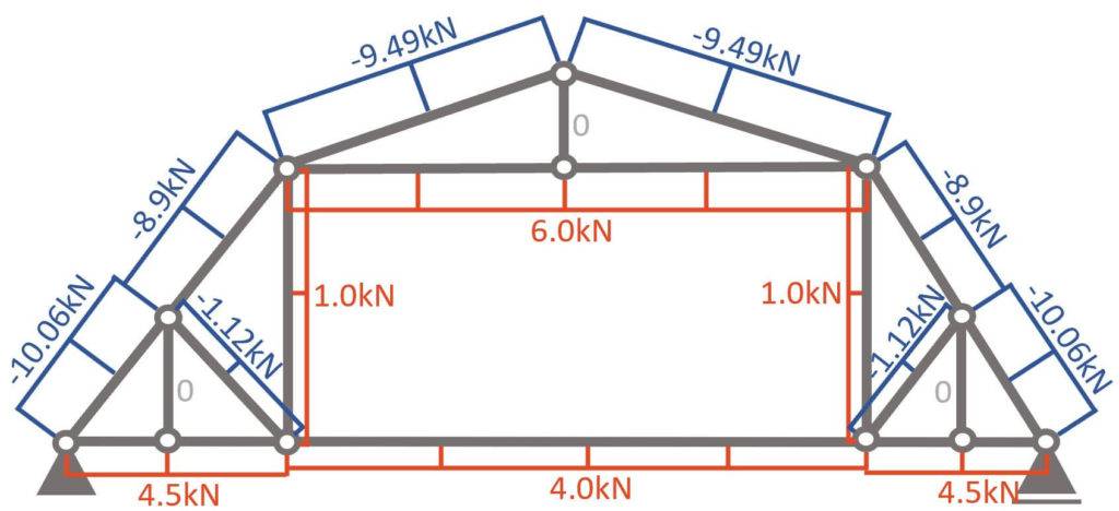
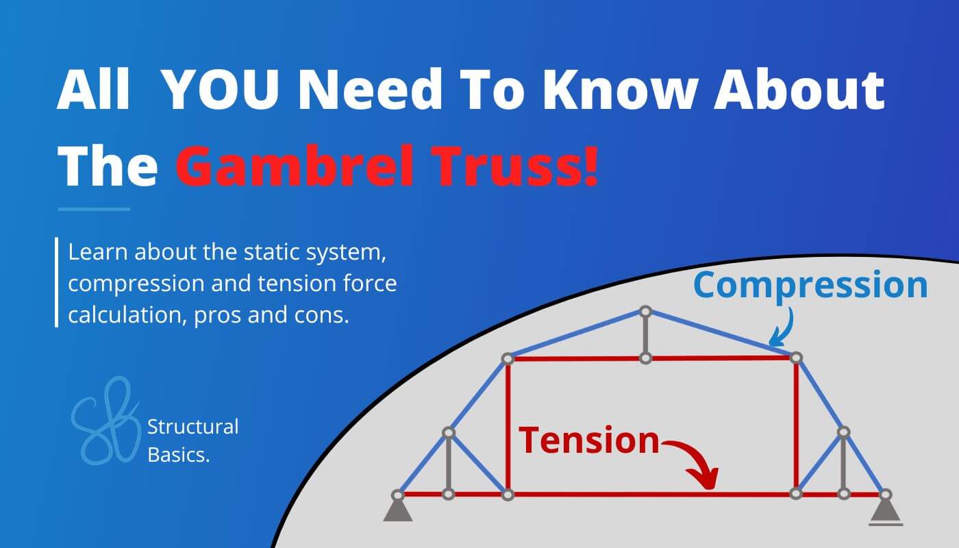
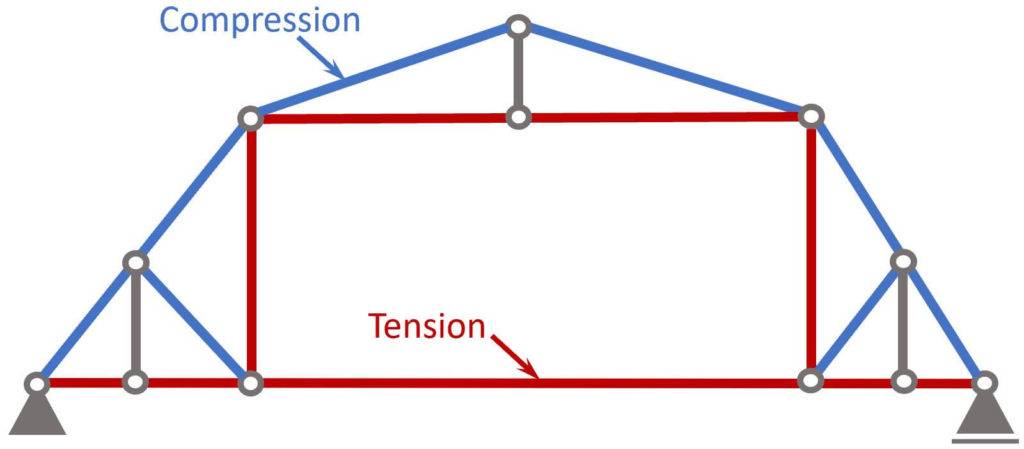
Compression and Tension Members
Now, as you can see in the normal force diagram, some members have a positive (+) and some have a negative (-) normal force.
A negative (-) normal force means that the member is under compression 🔵, while a positive (+) normal force means that the member acts in tension 🔴.
Advantages and Disadvantages
Pros
- Aesthetically pleasing structures: unique and attractive appearance
- Increased headroom: The steep upper slope of the gambrel truss provides additional headroom in the attic space, making it easier to move around and store items.
- Span: The gambrel truss can span longer than other types
Cons
- Many different connections
- Cost: The cost might be higher due to the complexity of its elements
However, the pros and cons depend on many factors and can vary for each structure or location.
Conclusion
Now, that you got an overview of the Gambrel Truss, and how we calculate its internal forces, you can learn about loads, because every truss is exposed to loads.
Because there are always multiple loads acting on Gambrel Trusses, considering these different loads in the structural design is done by setting up Load Combinations with safety factors.🦺
Once all load cases and combinations are set up, the structural elements can be designed. We have already written a guide on how to design a timber truss. Check it out!
If you want to learn more about trusses, make sure to read our guide on the different types of trusses.
I hope that this article helped you understand the Gambrel Truss and how to go further from here. In case you still have questions.
Let us know in the comments below ✍️.
Gambrel Truss FAQ
A gambrel truss is a type of roof truss that has two sloping sides on each of its two halves, creating a barn-like shape. It is commonly used in buildings such as barns, sheds, and some homes.
Gambrel trusses are typically constructed using wooden beams or steel rods that are connected at the joints using metal plates. The truss design allows for a larger open span and a steeper pitch than traditional roof designs.
![Understand Shear Forces [An Engineering Explanation]](https://www.structuralbasics.com/wp-content/uploads/2023/07/Shear-force-768x439.jpg)
![Arch – Moment And Normal Force Calculation Due To Line Load [A Guide]](https://www.structuralbasics.com/wp-content/uploads/2022/05/Arch-Structure-Internal-Force-Calculation-Due-To-Line-Load-768x439.jpg)